The menu bar encompasses several sections: File, Analysis, View, Windows, Setting, Tools, Help, and About.
File
 - Opening kpp file: Open the PhiPsi keywords file, i.e., *.kpp file.
 - Edit kpp file: Edit the PhiPsi keywords file.
 - Check kpp file: Check the PhiPsi keywords file.
 - Open work directory: Open work directory defined in the keywords file.
 - Open PhiPsi log file: Open PhiPsi running log file (*.log) which is stored in the work directory.
 - Clear result files: Clear result files of the current work defined in the keyword file.
 - Create a blank kpp file: Create a blank kpp file in a user defined folder.
 - Import Abaqus model (.inp): Import Abaqus model (.inp file). PPView will automatically transform the Abaqus model file to PhiPsi model files. The element information, node information, boundary conditions, external forces, and materials defined in the Abaqus model file will be handled. For 2D problems, the supported element types include CPS4, CPS4R, CPS4I, CES4, and CPE4R; For 3D problems, the supported element types include C3D8, C3D8R, C3D8H, C3D8I, C3D8RH, and C3D8IH. The supported loads include concentrated force and pressure. The extracted material parameters include elastic modulus, Poisson's ratio and density. Once the Abaqus model file has been read, PPView will automatically plot the model and update the kpp keyword file based on the extracted data.
 - Recent kpp file: Open recent kpp fles.
 - Export Plot: Save pictures, the following options are available:
 - Save Plot as Image: Save the current plot as image (*.png).
 - Save Plot as Image with White Background: Save the current plot as image (*.png) with white background.
 - Exit: Exit PPView.
 - Close and restart PPView: Close and restart PPView.
Analysis
 - Run kpp file with PhiPsi: Start the PhiPsi kernel to solve the problem defined in the keywords file.
 - Stop PhiPsi: Stop all running PhiPsi tasks.
 - Refresh results: Reload the result files of the currently running PhiPsi task.
View
 - Isometric: Plot in isometric view.
 - XY plane, (Z+): Plot in xy view (z plus).
 - XY plane, (Z-): Plot in xy view (z minus).
 - XZ plane, (Y+): Plot in xz view (y plus).
 - XZ plane, (Yz): Plot in xz view (y minus).
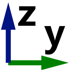 - YZ plane, (X+): Plot in yz view (x plus).
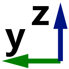 - YZ plane, (X-): Plot in yz view (x minus).
 - View cut manager: Open the view cut manager to plot user defined section view along the x, y, and z directions.
Windows
 - Minimize the Window: Minimize the Window.
 - Maximize the Window: Maximize the Window.
 - Fullscreen: Fullscreen the window.
 - Center: Center the window.
Setting
 - Model Display Style: Change model display style, the following display modes are available:
 - Mesh View: Display the model with mesh (default).
 - Smooth View: Display the model in a smooth view without mesh.
 - Wiremesh: Display the model only with wirelines.
 - Points: Display the model with only nodes.
 - Model Color: Change model color, the following options are available:
 - Cyan: All elements of the model will be drawn in Cyan.
 - Varies with Material Type: Elements with different material numbers are drawn in different colors.
 - Model Deformation Display Style: Change model deformation display style, the following display modes are available:
 - Mesh View: Display the deformed model with mesh (default).
 - Smooth View: Display the deformed model in a smooth view without mesh.
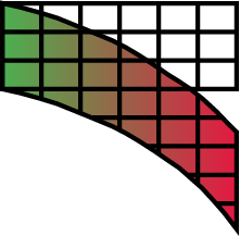 - Mesh View + Wiremesh (undeform): Display the deformed model with mesh and underformed wirelines.
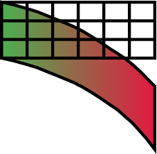 - Smooth View + Wiremesh (undeform): Display the deformed model in a smooth view without mesh and underformed wirelines.
 - Crack Display Style: Change crack Display style, the following options are available:
 - Mesh View (for 3D): Display 3D cracks with mesh.
 - Smooth View (for 3D): Display 3D cracks in a smooth view without mesh.
 - Show Model Wiremesh: Show model wiremesh.
 - 2D Crack Color: Change color of 2D cracks - Balck (default) / White / Read / Purple.
 - 2D Crack Width: Change width of 2D cracks - 1 / 2 (default) / 3.
 - Show 2D Crack Points: Display 2D crack points.
 - Pre-exsisting Natural Cracks: Settings about pre-exsisting natural cracks: Plot Pre-exsisting Cracks as Surface (3D) (default), Plot Pre-exsisting Cracks as Wireframe (3D), or Hide Pre-exsisting Cracks.
 - Enriched Nodes Display Style: Change the Display style of enriched nodes - Size 2 / Size 4 / Size 6 (default) / Size 8.
 - Enable Lighting: Enable lighting.
 - Enable Parallel Projection: Enable parallel projection, switch the visualization mode of a 3D scene from perspective projection to parallel projection.
 - Enable Model Transparent: Make the 3D model transparent, enabling users to see through the model's surfaces.
 - Show Model Boundary Box: Allows users to visually display a bounding box around the model.
 - Show Load: Plot the applied force of nodes.
 - Show Boundary Support: Display the supporting of fixed nodes.
 - Show Model Coordinate Origin: Display the coordinate origin of the model.
 - Animation: Animation-related settings.
 - Background Color: Change background color, the following options are available:
 - Gradient Grey.
 - Gradient Blue.
 - Gradient Green.
 - Gradient Yellow.
 - Gradient Purple.
 - Gradient Black.
 - Select a Solid Color.
 - Theme: Change theme of icons or font:
 - Chaneg icon theme. The following options are available:
 - Green icon theme (default).
 - Blue icon theme.
 - Change font theme.
 - Colorbar Colormap: Change colormap of colorbar. The following options are available:
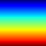 - Jet.
 - PiYG.
 - Greys.
 - hsv.
 - cool.
 - ocean.
 - spring.
 - summer.
 - autumn.
 - winter.
 - Blues.
 - Reds.
 - Greens.
 - Purples.
 - pink.
 - Oranges.
 - copper.
 - YlGn.
 - YlOrRd.
 - cividis.
 - inferno.
 - magma.
 - plasma.
 - viridis.
 - Accent.
 - Paired.
 - tab20.
 - Colorbar Font: Change font of colorbar.
 - Text Editor: Change text editor - Notepad (default) / Notepad ++ (if installed).
 - PhiPsi Solver: Change PhiPsi solver, the following options are available:
 - PhiPsi Solver Compiled Using gfortran (default): Simulation will be porformed by running PhiPsi_Win64.exe (C:\Program Files (x86)\PhiPsi\PPView\PhiPsi\PhiPsi_Win64.exe) compiled using gfortran.
 - PhiPsi Solver MPI Version. Simulation will be porformed by running PhiPsi_Win64_MPI.exe (C:\Program Files (x86)\PhiPsi\PPView\PhiPsi\PhiPsi_Win64_MPI.exe).
 - Set Number of MPI Processors. Set the bumber of MPI processors for PhiPsi_Win64_MPI.exe.
Tools
 - PhiPsi Running Monitor: Run the PhiPsi running monitor to watch the memory and CPU usage of the PhiPsi kernel.
 - Run a Batch File: Run a batch File (*.bat).
 - Run a Python Script: Run a Python script (*.py).
 - Open PhiPsi kpp File Editor: Open the PhiPsi kpp file editor that comes with the PPView software.
Help
 - PPView Help: Open the online PPView help manual.
 - PhiPsi Instruction Manual: Open the online PhiPsi instruction manual.
 - PhiPsi Keywords Manual: Open the online PhiPsi keywords manual.
 - View Change Log of PPView: View change logs of PPView.
About
 - About: About PPView.
 - PhiPsi Website: Visit PhiPsi Website - phipsi.top.
 - Check for updates: Check for updates of PPView.